
In this article, we will tell you about one more method of circuit analysis, which is called the Node Voltage Method. It also allows to reduce the calculations and save the time when we do the circuit analysis. Let’s firstly consider the T-circuit scheme from our previous post and solve it with the help of the Node Voltage Method.
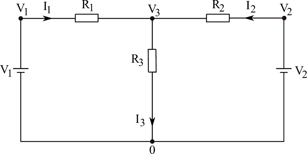
Let the first voltage source (or the battery) be 10\ V and the second one – 15\ V. Let the resistances be R_1 = 15\ \Omega, R_2 = 22\ \Omega and R_3 = 30\ \Omega. Our task is to analyze the circuit and find the currents I_1, I_2, I_3 and the voltage drops on resistances R_1, R_2, R_3.
Let’s now choose the node marked as “0” as a reference point as shown in the picture above. Then, the other three nodes will have the voltages V_1, V_2 and V_3 with respect to that reference point. We already know the voltages V_1 and V_2. To find V_3, we need to apply the Kirchhoff’s Current Law:
I_1 + I_2 = I_3.
Then, applying the Ohm’s law we get:
\dfrac{V_{R1}}{R_1} + \dfrac{V_{R2}}{R_2} = V_{R3},
here, V_{R1}, V_{R2} and V_{R3} are the potential differences between the nodes (or voltage dropes across the resistors which is the same). These potential differences can be found in a following way (since we choose the node marked as “0” as a reference point, V_{0} will be equal to 0\ V):
V_{R1} = V_1 – V_3,
V_{R2} = V_2 – V_3,
V_{R3} = V_3 – V_0 = V_3
Substituting V_{R1}, V_{R2} and V_{R3} into the previous formula, we obtain:
\dfrac{V_1 – V_3}{R_1} + \dfrac{V_2 – V_3}{R_2} = \dfrac{V_3}{R_3}.
Let’s substitute the numbers:
\dfrac{10 – V_3}{15} + \dfrac{15 – V_3}{22} = \dfrac{V_3}{30}.
From this equation we can find the unknown voltage V_3:
22\times 30 \times (10-V_3) + 15\times 30 \times (15-V_3) = 15\times 22 \times V_3,
V_3 = 9.3\ V.
Then, from the Ohm’s law we can find the currents through all resistors:
I_1 = \dfrac{V_1 – V_3}{R_1} = \dfrac{10\ V – 9.3\ V}{15\ \Omega} = 0.05\ A,
I_2 = \dfrac{V_2 – V_3}{R_2} = \dfrac{15\ V – 9.3\ V}{22\ \Omega} = 0.26\ A
I_3 = \dfrac{V_3}{R_3} = \dfrac{9.3\ V}{30\ \Omega} = 0.31\ A
Finally, we can find the voltage drops on resistances R_1, R_2, R_3:
V_{R1} = V_1 – V_3 = 0.7\ V
V_{R2} = V_2 – V_3 = 5.7\ V
V_{R3} = V_3 = 9.3\ V
Thus, as you can see, there is nothing difficult in circuit analysis using the Node Voltage Method and we always glad to help you.

